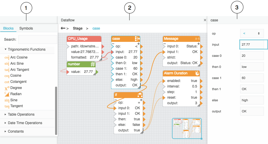
...Pin a property?
To ensure that a property remains displayed when you select other objects (for example, to bind to the property), you pin it. To pin a property of a block, hover over the property in the properties panel until a blue dot appears, then click the blue dot and check Pinned.
...Bind to a List property of a component?
If you want to control a component property programatically and the property is displayed as a drop-down list, you need know the internal values that correspond to the options displayed in the list. For example, the layout of the stage can only be absolute, vertical, or horizontal. To determine the internal values used by a list property, select the desired value from the drop-down list, bind it to a property of a block, then unbind it. The following video shows you how to do this.
...Rename a block?
Double-click the block heading text and enter the desired name. Note that this name is for display only. Blocks also have a system name that is used for binding, and by default the system name is not affected when you change the display name. To change both the display name and the system name, edit the text and type CTRL-ENTER to save. System names cannot contain spaces or special characters, and must be unique. If you change the system name of a block that has bindings, you must correct the bindings to use the new name.
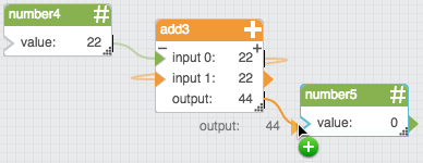
...Connect blocks across dataflows?
You can view only one dataflow at a time. To connect blocks that reside in different dataflows, pin the properties of the target block, then switch to the dataflow containing the source block and connect them.
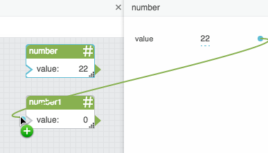
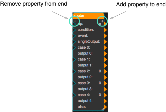
...Add properties to a block?
To add a property to a block, click the plus sign (+) that is displayed on the block. The new property is added to the end of the list of properties and, if the block permits user-named properties, you are prompted for its name.
To add a property in a specific position in the list, right-click a property in the Properties panel and choose Add Parameter Before or Add Parameter After.
To delete a previously-added property from a block, right-click the property in the Properties panel and choose Remove Parameter.